TIME RESOLVED MAGNETO-OPTICAL KERR EFFECT (TRMOKE) MICROSCOPE
Time-resolved magneto-optical Kerr effect (TRMOKE) microscope is a very powerful technique for the time-domain measurement of the ultrafast magnetization dynamics of magnetic thin films, multilayers and patterned micro and nanostructures. In TRMOKE, magnetization dynamics is excited either by a pulsed magnetic field or by a femtosecond laser pulse. The dynamics is detected by a plane polarized femtosecond laser pulse, which probes the magneto-optical Kerr rotation as a function of the time-delay between the pump and probe beams. Eversince its introduction in 1991 the TRMOKE technique has continued to evolve to meet the requirements of applications of this technique to various samples and for measuring different magnetic properties. In our laboratory, we have developed an all-optical TRMOKE microscope with a two-colour collinear and micro-focused pump-probe geometry. This enabled us to achieve a spatial resolution of ~ 700 nm combined with a time resolution of ~ 100 fs. The detection technique (optical bridge detector) enables to achieve a measurement sensitivity of ~ mdeg.
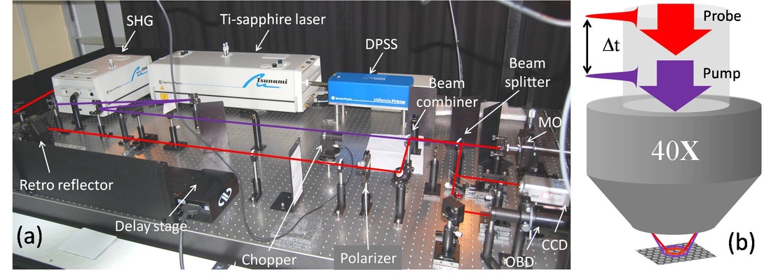
Fig.: (a) A photograph of the all-optical TRMOKE set up with collinear microfocused pump-probe geometry. (b) The collinear pump-probe geometry is shown schematically.
Our TRMOKE microscope
(Fig. (a)) is based upon a mode-locked Ti-sapphire laser with 80 MHz repetition
rate, ~ 80 fs pulse width, tunable wavelength between 700 and 1100 nm and with
energy of 25 nJ/pulse. The output is usually fixed at around 800 nm for a
stable operation and a better detector response. A part (70%) of output beam from
the Ti-sapphire laser is frequency doubled (l = 400 nm) by passing through a second harmonic generator (SHG),
which is used to pump the magnetization dynamics whereas the linearly polarized
fundamental laser beam (l = 400 nm) is used for probing the dynamics. The pump beam travels
through a fixed optical path while probe beam travels through a variable delay
line with a broadband hollow retroreflector. The probe beam is expanded and
collimated by sending through a beam expander and is then made linearly
polarized by passing through a Glan-Thomson polarizer. Subsequently the probe
beam is combined with the pump beam by a beam combiner and from the point of
beam combination, the pump and probe beams are made perfectly collinear with
the steering mirrors.
The probe beam is focused to a spot size of ~700 nm and placed at the centre of an array by a microscope objective with numerical aperture N. A. = 0.65 and a closed loop piezoelectric scanning x-y-z stage. The pump beam is spatially overlapped with the probe beam after passing through the same microscope objective in a collinear geometry. Consequently, the pump spot is slightly defocused (spot size ~ 1 µm) on the sample plane, which is also the focal plane of the probe spot. The probe spot is placed at the centre of the pump spot as shown in Fig. (b). A large magnetic field is first applied at a small angle (~ 10-15°) to the sample plane to saturate its magnetization. The magnetic field strength is then reduced to the bias field value, which ensures that the magnetization remains saturated along the bias field direction. The bias field was tilted out at a small angle from the plane of the sample to have a finite demagnetizing field along the direction of the pump pulse, which is eventually modified by the pump pulse to induce precessional magnetization dynamics within the dots. The pump beam was chopped at 2 kHz frequency and a phase sensitive detection of the Kerr rotation was used. For out-of-plane magnetized samples the bias field is applied at a small angle from the normal to the sample plane. The sample is also scanned under the focused pump and probe spots at fixed time delays to obtain dynamic magnetic images. The time-resolved Kerr rotation is measured as a function of the strength and orientation of the bias magnetic field and different sample parameters.
The probe beam is focused to a spot size of ~700 nm and placed at the centre of an array by a microscope objective with numerical aperture N. A. = 0.65 and a closed loop piezoelectric scanning x-y-z stage. The pump beam is spatially overlapped with the probe beam after passing through the same microscope objective in a collinear geometry. Consequently, the pump spot is slightly defocused (spot size ~ 1 µm) on the sample plane, which is also the focal plane of the probe spot. The probe spot is placed at the centre of the pump spot as shown in Fig. (b). A large magnetic field is first applied at a small angle (~ 10-15°) to the sample plane to saturate its magnetization. The magnetic field strength is then reduced to the bias field value, which ensures that the magnetization remains saturated along the bias field direction. The bias field was tilted out at a small angle from the plane of the sample to have a finite demagnetizing field along the direction of the pump pulse, which is eventually modified by the pump pulse to induce precessional magnetization dynamics within the dots. The pump beam was chopped at 2 kHz frequency and a phase sensitive detection of the Kerr rotation was used. For out-of-plane magnetized samples the bias field is applied at a small angle from the normal to the sample plane. The sample is also scanned under the focused pump and probe spots at fixed time delays to obtain dynamic magnetic images. The time-resolved Kerr rotation is measured as a function of the strength and orientation of the bias magnetic field and different sample parameters.
References
- M. R. Freeman, R. R. Ruf, and R. J. Gambino, IEEE Trans. Magn. 27, 4840 (1991).
- R. J. Hicken, A. Barman, V. V. Kruglyak, and S. Ladak, J. Phys. D: Appl. Phys. 36, 2183 (2003).
- A. Barman, S. Wang, J. D. Maas, A. R. Hawkins, S. Kwon, A. Liddle, J. Bokor, and H. Schmidt, Nano Lett. 6, 2939 (2006).
- A. Barman, T. Kimura, Y. Otani, Y. Fukuma, K. Akahane, and S. Meguro, Rev. of Sci. Instrum., 79, 123905 (2008).
- B. Rana, D. Kumar, S. Barman, S. Pal, Y. Fukuma, Y. Otani, and A. Barman, ACS Nano 5, 9559 (2011).
